
Project Overview
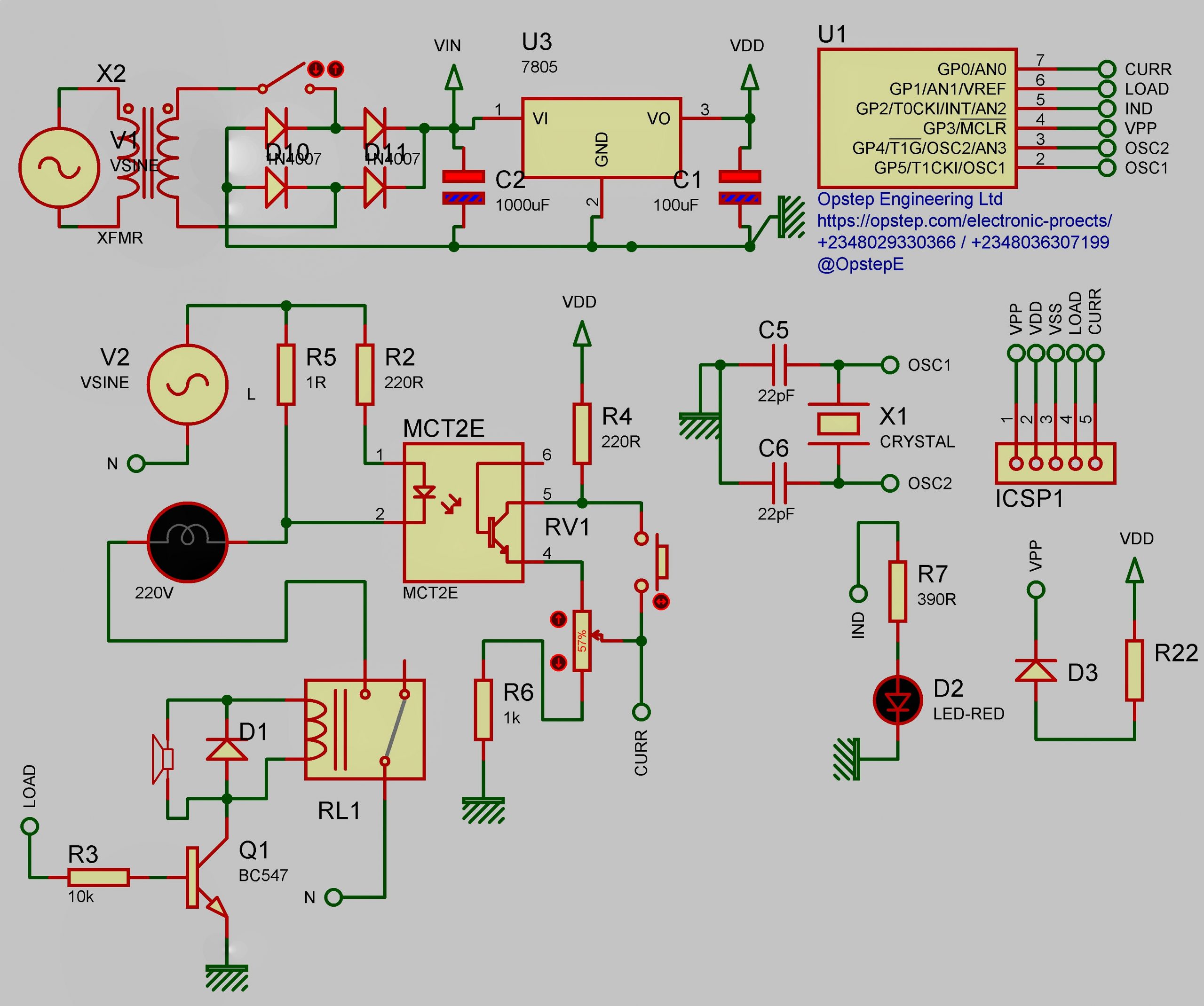
This system can sense the overload condition and breaks the power if the load increases above the set point. It is an ideal circuit to protect uninterrupted power supply device like inverter, home appliances. Mode of working: The optocoupler MCT2E and resistor (1 ohm 5watt) will do the trick. The Optocoupler has an LED and a phototransistor inside with connecting leads. The LED of MCT2E is connected parallel to the resistor with a current limiter for the LED. The phototransistor of the optocoupler is connected to transformer derived 5 volt DC through the current limiting resistor.
The load is connected through the common and normally close contact of the relay, so it will work normally at power on. As the load switches on, current flows through the 1 ohm resistor depending on the current drawing by the load. This changes the brightness of the LED inside the optocoupler which on turn control the biasing of the phototransistor. The emitter current of the phototransistor thus depends on the brightness of LED which in turn depends on the current flowing through the 1 ohm resistor.
When the load current increases, a corresponding current flows increase through the 1 ohm resistor and a corresponding potential difference develops across it. When the load current increases to maximum, the voltage at the variable resistor increases enough to bias the input to the microcontroller, the relay then turns on, the buzzer beeps to indicate the overload condition. The relay remains energized due to the latching action of the controller and it can be de-energized after removing the excess load and pressing the reset switch.
To set the circuit for the desired tripping point, we use a five, 100 watt bulbs as load, if maximum is 300 watt is the desired tripping point, then we use three 100 watt bulbs as load and slowly turn the variable resistor till the relay energizes and the lamps turn off. At this point, buzzer beeps. Then we remove one bulb and reset the system using the reset button, load will switch on normally, again connect the bulb as load when it switches on the relay will cut the load.
How the System Works
- The system is described in the historical project documentation preserved for this project.
- The documented inputs, controller or processing stages receive and process the relevant project signals.
- The controller or circuit performs the functions described in the original project material.
- The documented outputs provide the project response, indication or control.