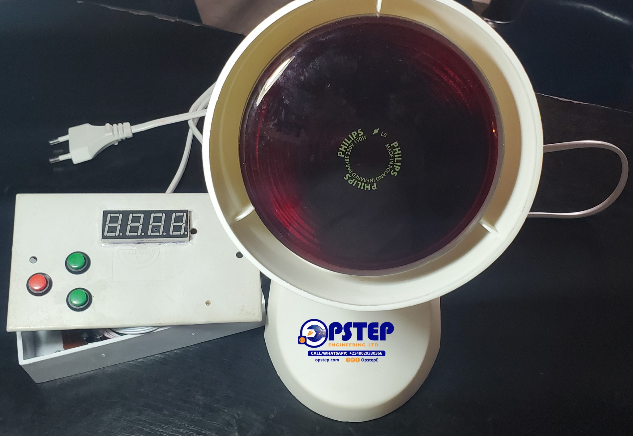
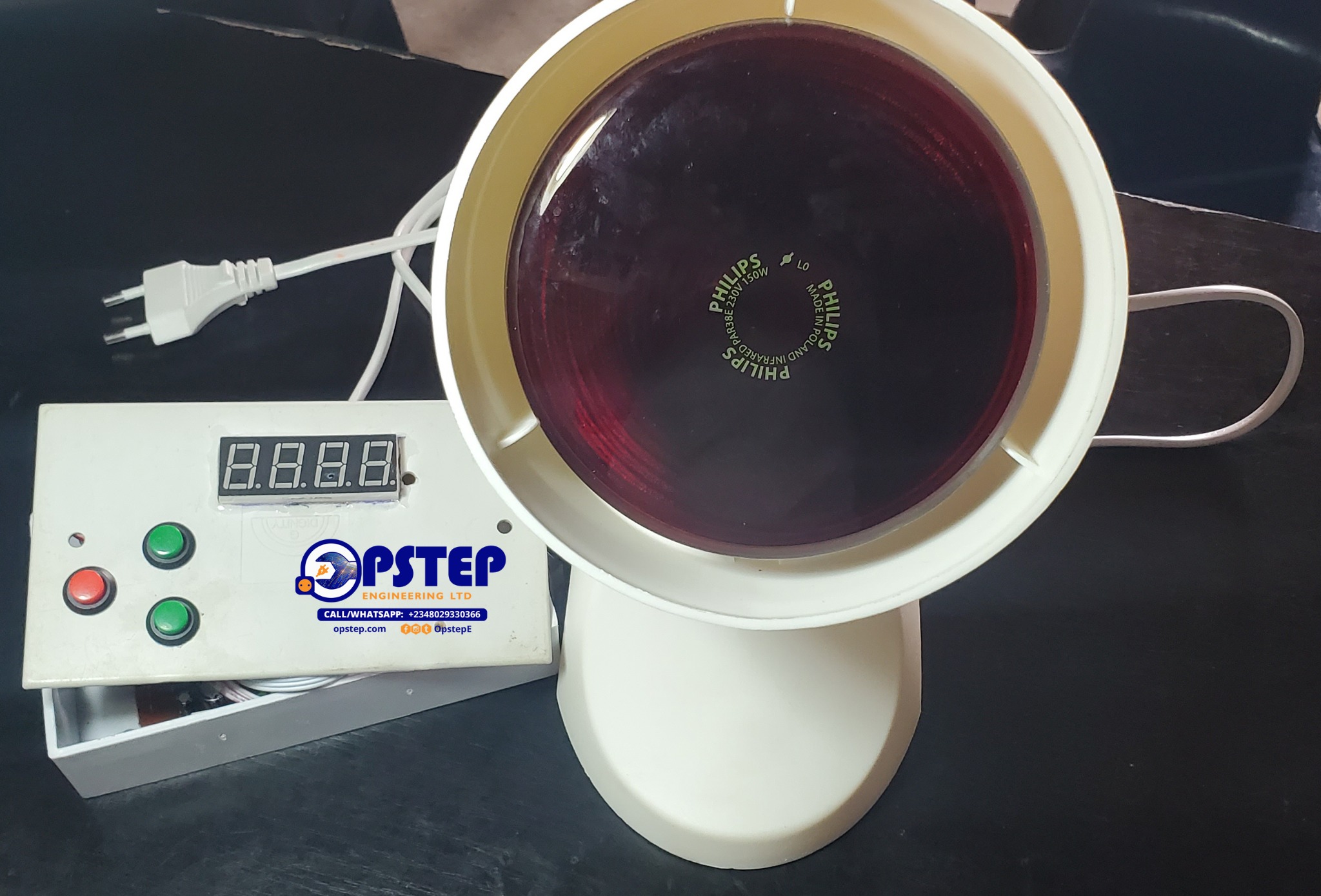
Project Overview
The Digital Countdown Timer for Phototherapy Light is a microcontroller-based timing and control system designed to provide precise, user-settable treatment durations for phototherapy light sessions.
The system supports a configurable countdown from 1 second to 9999 seconds, with the remaining time displayed on a four-digit multiplexed 7-segment display. At the end of the countdown, the relay is de-energized to switch off the connected phototherapy light.
How the System Works
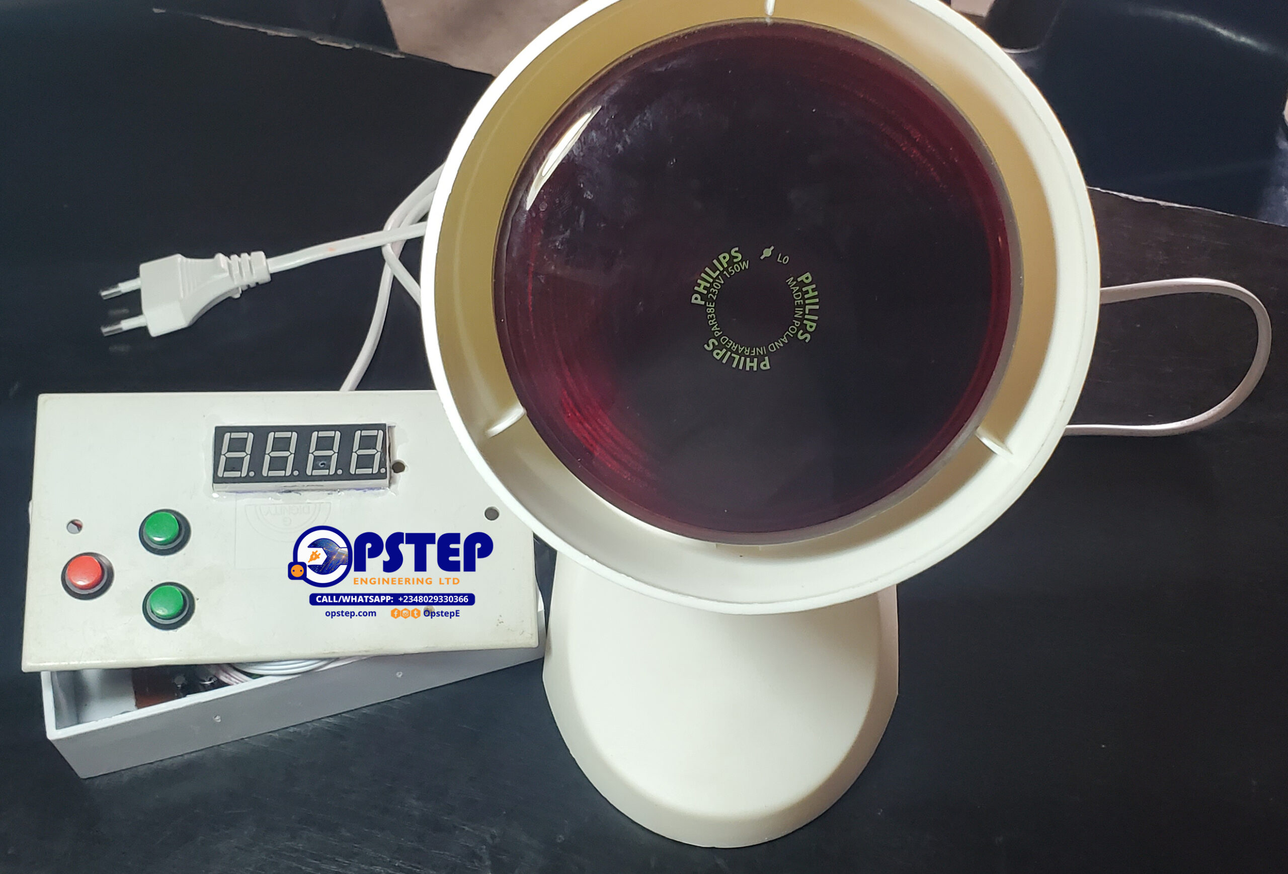
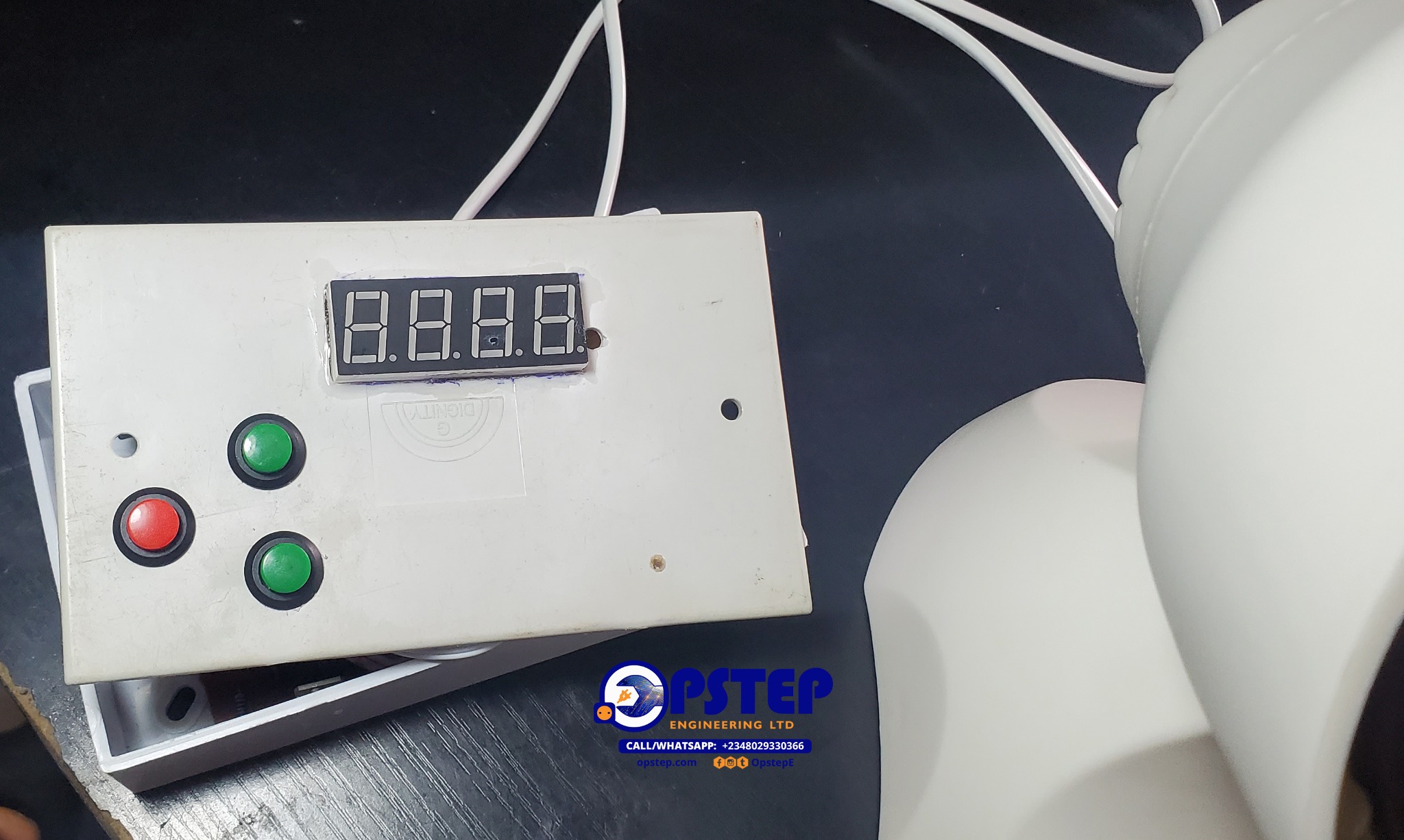
- SET / MODE — enters the time-setting mode.
- UP / INCREMENT — adjusts the selected time.
- START / STOP — begins or pauses the countdown.
The selected duration is shown on the four-digit display while the controller manages the countdown. When the countdown reaches zero, the relay is de-energized to switch off the connected light.
System Architecture
Control Logic
Light
Circuit Diagram
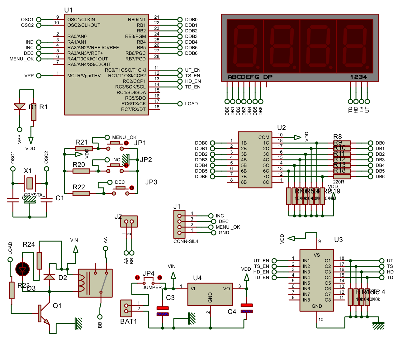
Embedded Control
The PIC16F876A provides the embedded control logic for the timer. The documented firmware manages user input, countdown timing, display operation, start/stop control and relay control.
Display Multiplexing
The four-digit display is multiplexed so that the controller can drive the display while retaining the I/O resources required for the other system functions.
Relay Control
The documented output stage uses a BC547 transistor to drive the relay, with a 1N4007 diode providing flyback protection for the relay coil.
Power Supply
The documented design uses a 12 V DC input and an LM7805 regulator to provide a regulated 5 V rail for the controller and display logic.
Project Video
Project Gallery
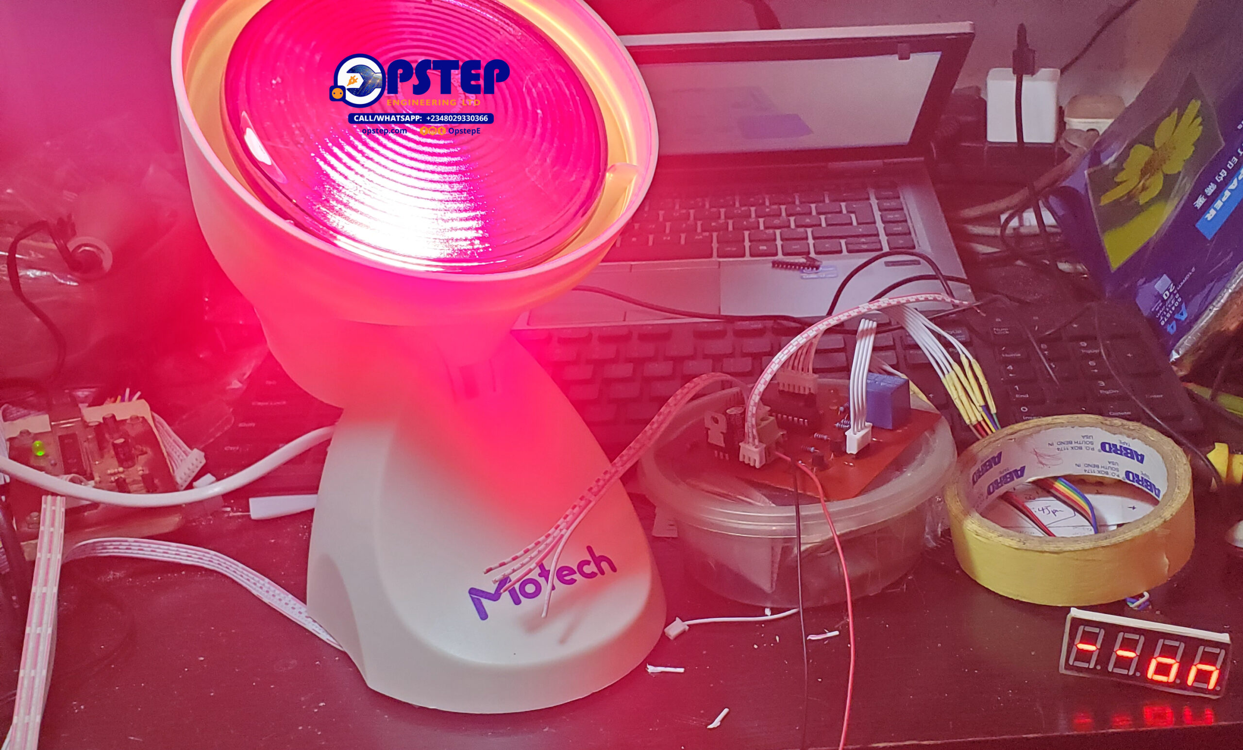
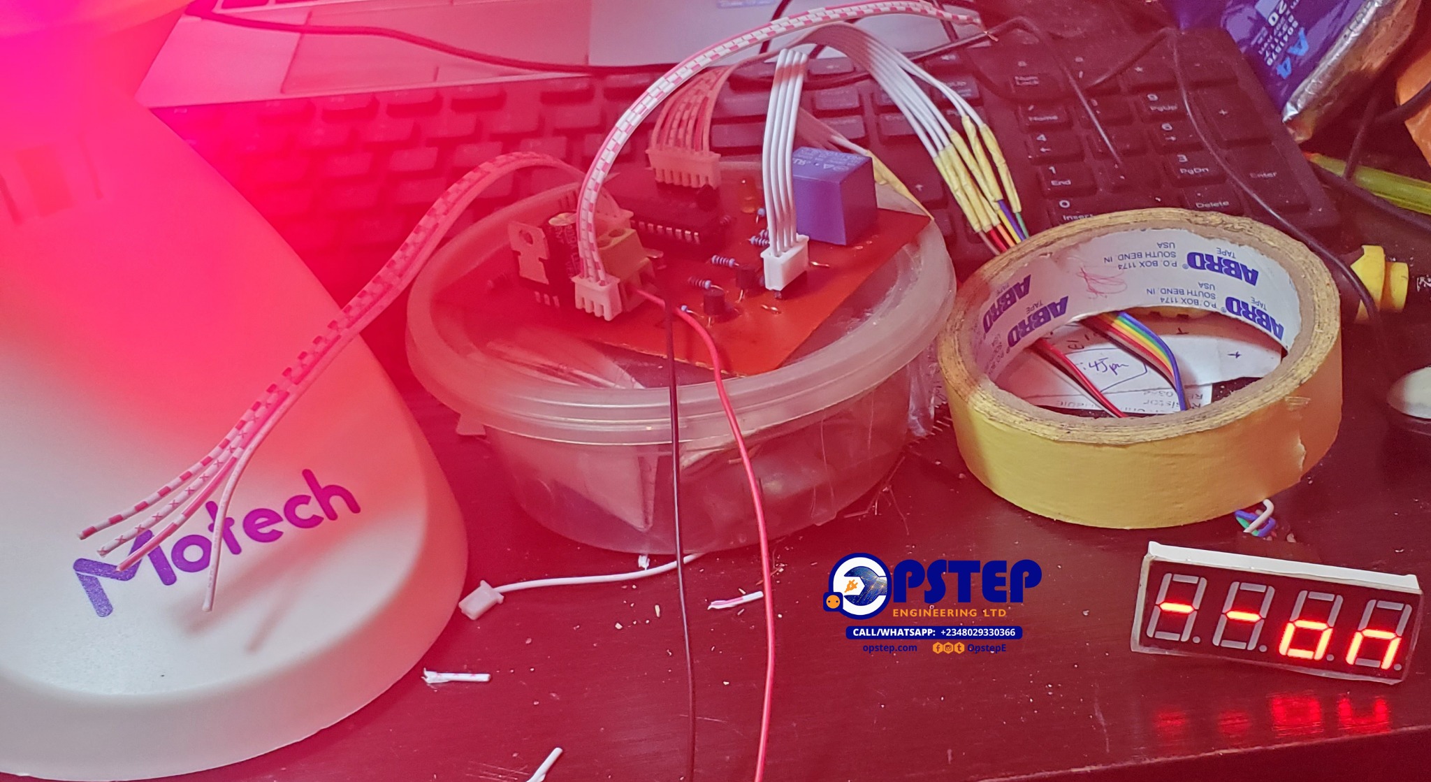
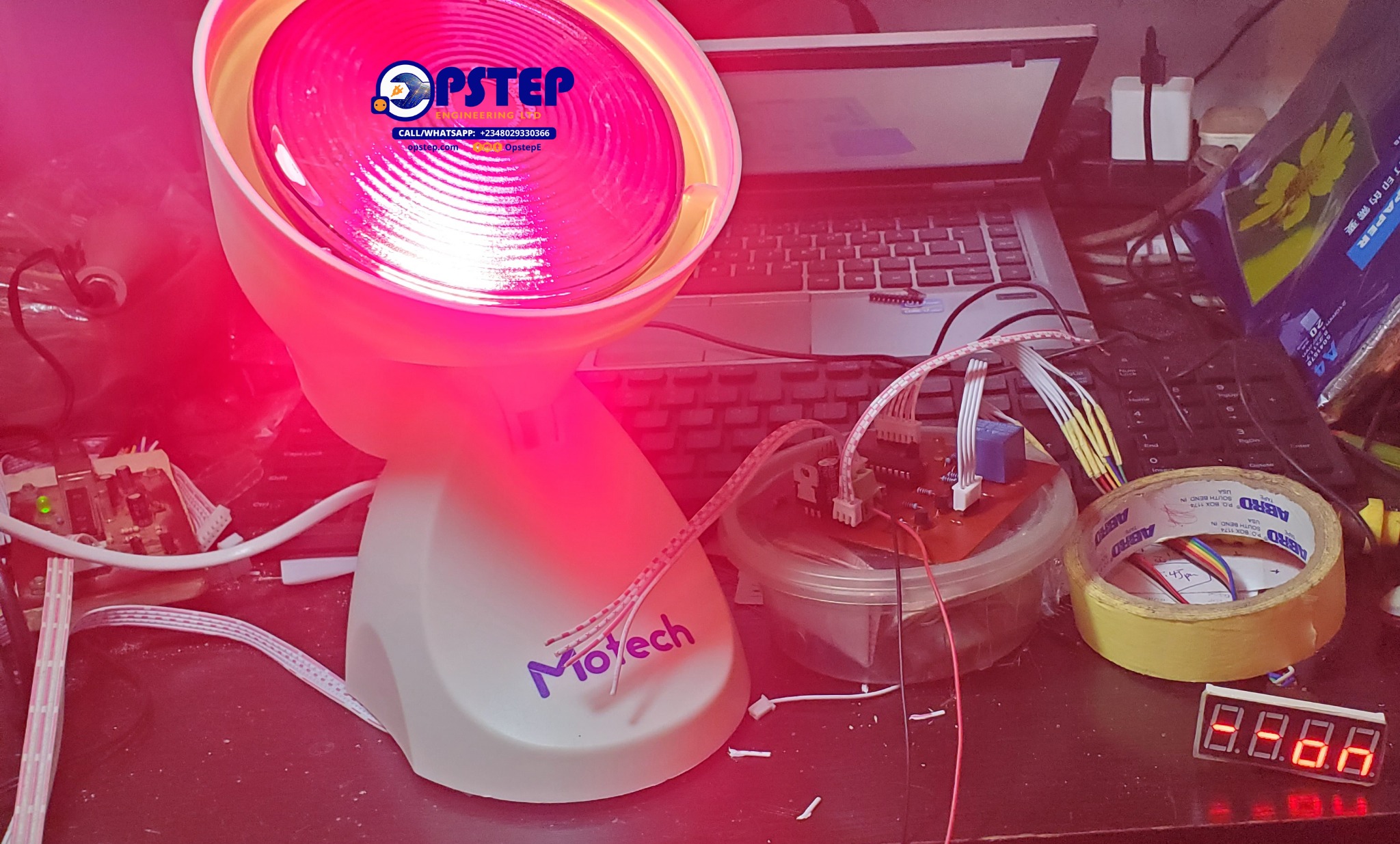
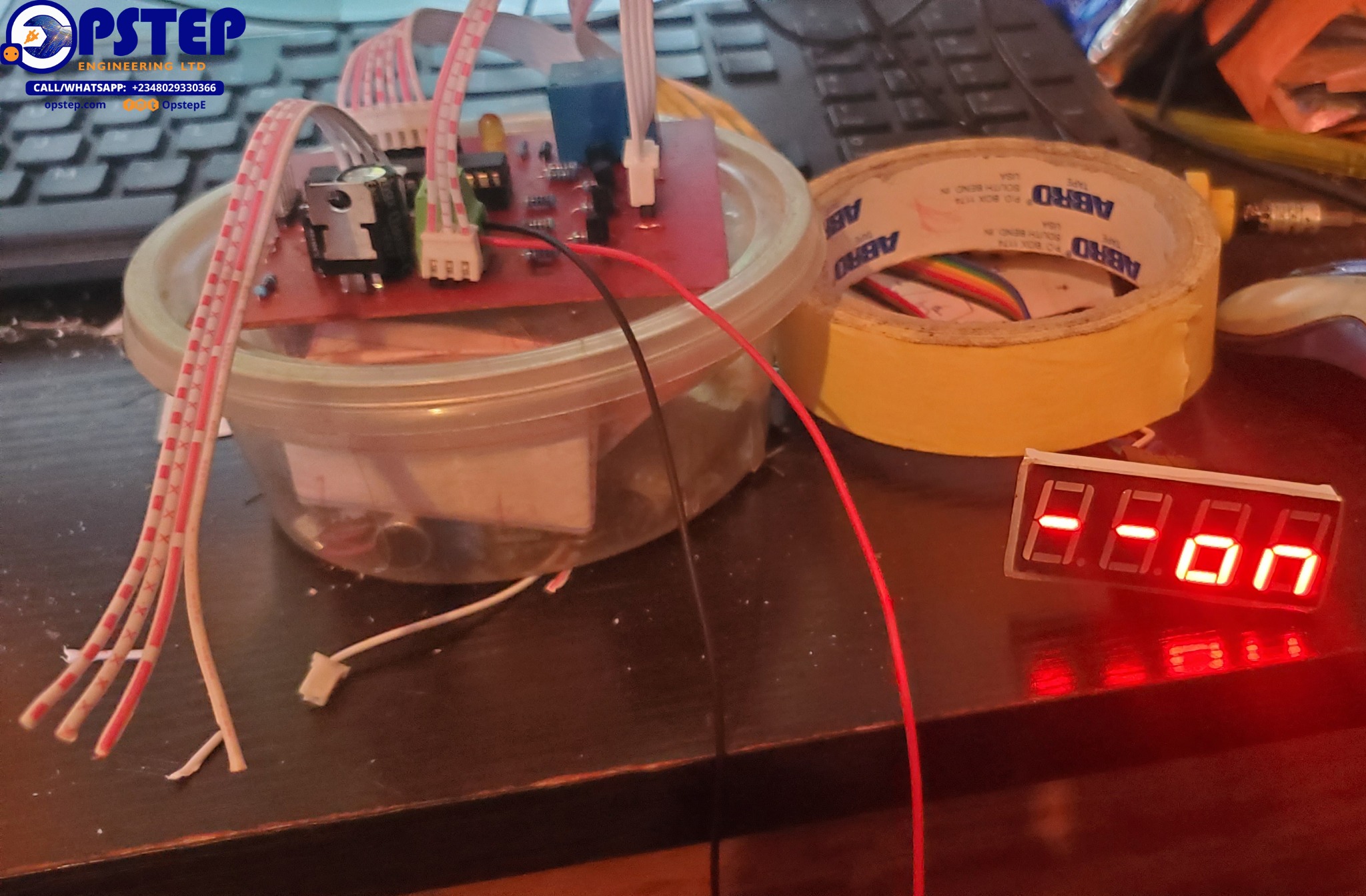
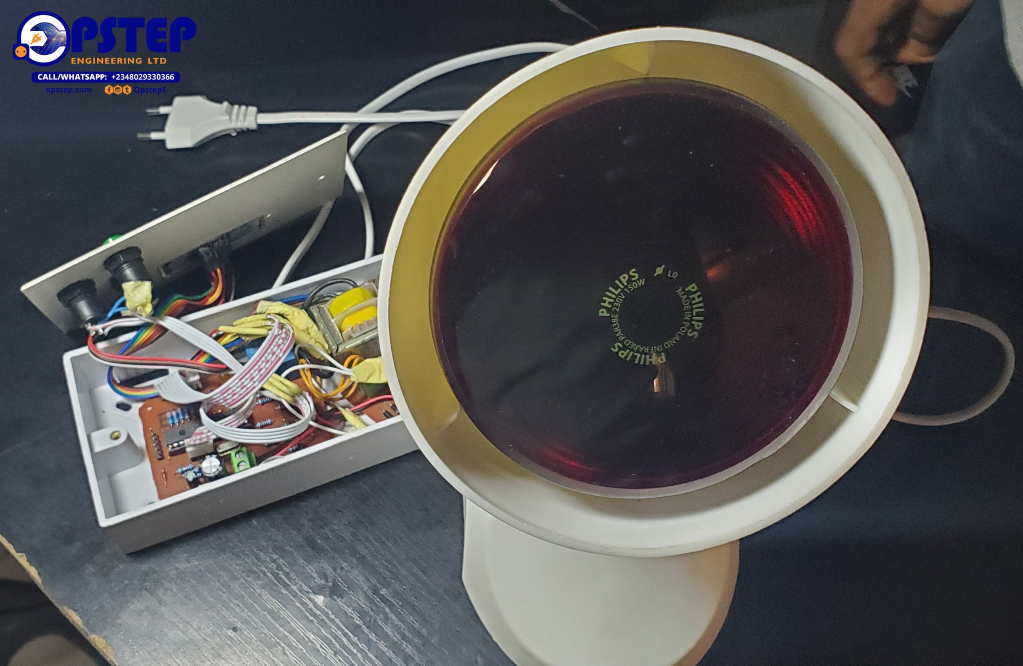
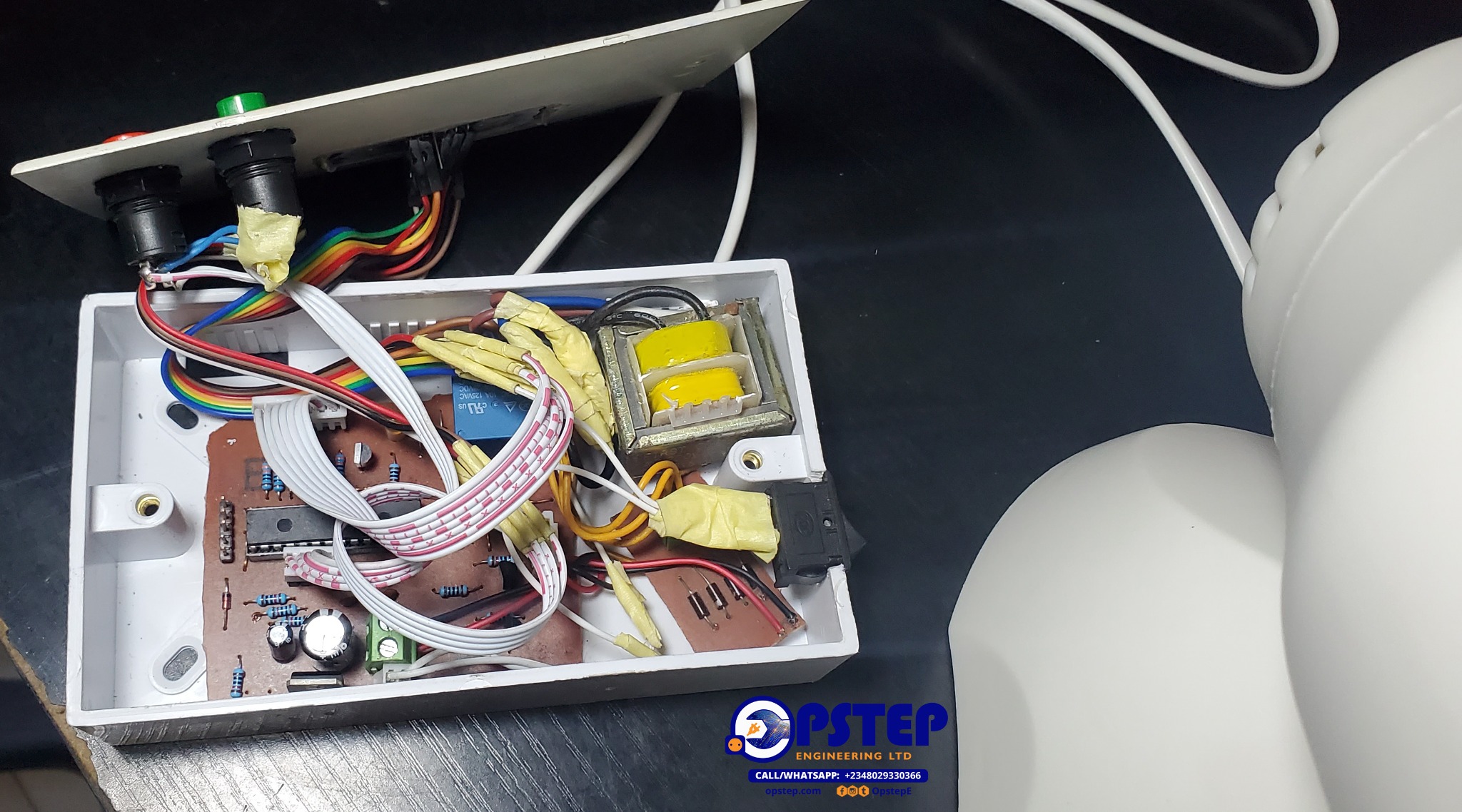
Actual project photographs and technical images.