
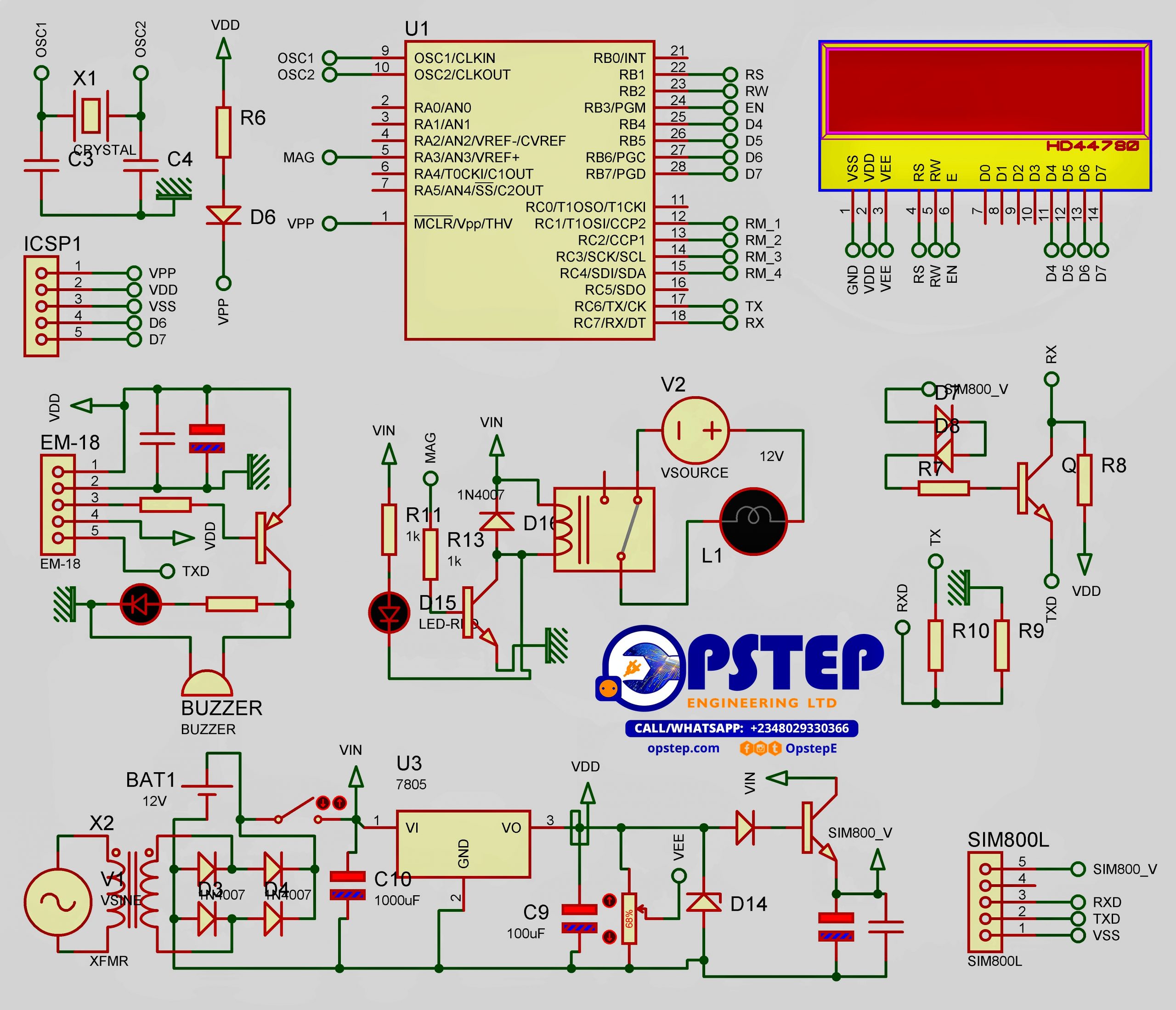
Project Overview
This material discusses the design of a keyless security system. The system aims to achieve an entry means to a secured location, not through the use of keys but through a wireless means and to achieve this, an RFID reader and tags were obtained for use. RFID stands for radio frequency identification, with a reader called EM-18 RFID Reader Module which is one the most commonly used module for Radio Frequency Identification Projects. It features Low Cost, Small Size, Low Power Consumption and Easy to use. It can be directly interfaced with microcontrollers using UART communication.
Software UART can be used for microcontrollers having no UART modules. In this material we will see how the Interfacing between the EM-18 RFID Reader Module with PIC 16F876A Microcontroller was achieved. By understanding the basic idea, you will be able to interface it with any microcontrollers. The EM-18 RFID Reader module generates and radiates RF Carrier Signals of frequency 125 KHz through its coils. When a 125KHz Passive RFID Tag (have no battery) is brought in to this field, will get energized from it. These RFID Tags are usually made using a CMOS IC EM4102.
It gets enough power and master clock for its operations from the electromagnetic fields produced by RFID Reader. By changing the modulation current through the coils, tag will send back the information contained in the factory programmed memory array. EM-18 RFID Reader Module can be directly interfaced with 5V PIC Microcontrollers using UART module. For 3.3V device you need to add additional voltage divider resistors to reduce 5V to 3.3V. You may also use Software UART if a dedicated UART module is not available. When a RFID Tag is brought in to the field of EM-18 RFID Reader, it will read its tag number and give output via TX terminal.
The BEEP terminal will become LOW to indicate valid tag detection. The UART output will be 12 ASCII data, among these first 10 will be tag number and last 2 will be XOR result of the tag number which can be used for error testing. For e.g: If the RFID tag number is 500097892E, output of EM-18 Reader will be 500097892E60 where 60 is 50 xor 00 xor 97 xor 89 xor 2E. Note that TX of RFID Reader is connected to the RX of microcontroller. When a 125 KHz RFID tag is bring in to the field of Reader Module, BEEP terminal becomes low. This will turns on the Buzzer and LED. Meantime RFID tag data will be send to microcontroller via UART.
RFID (Radio frequency identification) systems use data strings stored inside RFID tags to uniquely identify people or objects when they are scanned by an RFID reader. These types of systems are found in many applications such as passport protection, animal identification, inventory control systems, secure access control systems, robotics, navigation, inventory tracking, payment systems, and car immobilization.
The distance over which the RFID tag is usable is affected by such things as the tag shape and size, materials being used in the area near the reader, and the orientation of the reader and tag in respect to each other and in their operating environment. Coupled with this is that an attached LCD is available on the system to display what card id is brought into the reader’s field. The screen enables user interacts with the system successfully. For every card that must have the ability to gain entry access, such cards id must have been stored in the system’s database.
For the purpose of the system only three cards were used and only one card can unlock the door into a specific door. So card one only access room one, card two room two, card three room three. If any card whose id has not been preprogrammed into the system’s database and has been allocated a room number, such card will be regarded as an invalid card and no access will be granted such to any door. While the LCD gives notification of a valid card, an invalid card, the system also got attached a phone module which continuously sends feedback to an already preprogrammed phone number of every activity within and around the system.
When a registered card with a room address is brought to the reader field, the system scans the card, verifies its existence and if valid, notifies a user via the screen and also sends a text message to the feedback number of an entry access granted to what card and into what room, also, when an unregistered card is brought whose id is been scanned and not found in the database of the system, an invalid message is displayed on the screen for the user while a text message is dent to the feedback number of the happening also.
How the System Works
- The system is described in the historical project documentation preserved for this project.
- The documented inputs, controller or processing stages receive and process the relevant project signals.
- The controller or circuit performs the functions described in the original project material.
- The documented outputs provide the project response, indication or control.