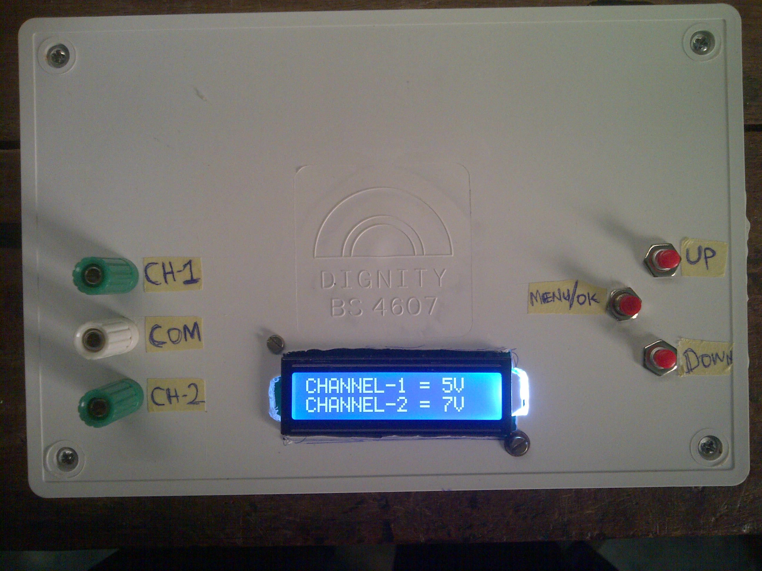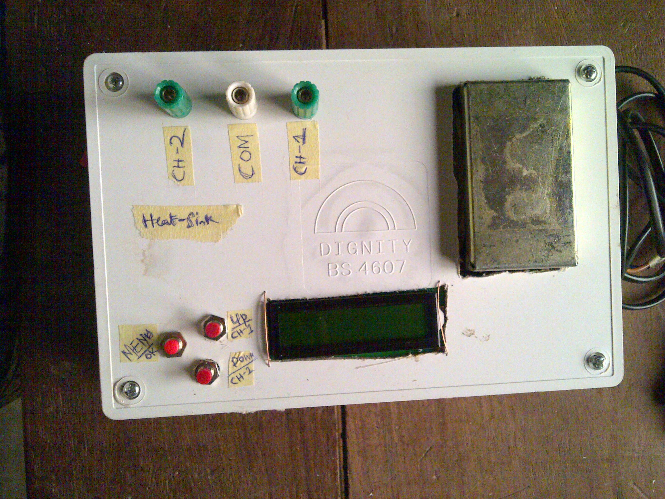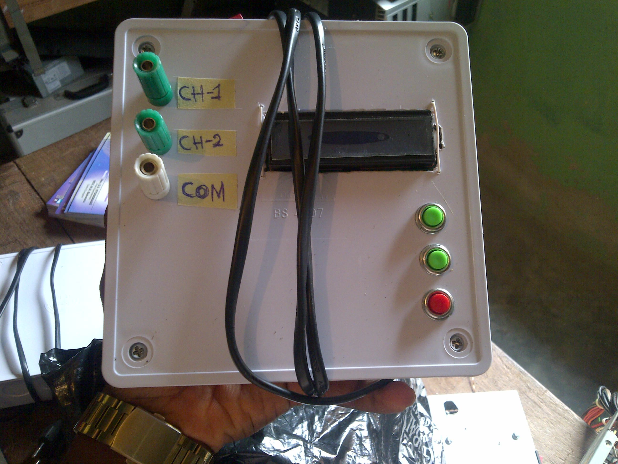

Project Overview
This project describes a two-channel digital variable power supply intended for laboratory and workbench use, with a documented output range of 0 to 15 V DC.
The design uses a microcontroller PWM output, LM358 operational-amplifier circuitry and a TIP122 power stage to regulate the output according to user-selected values. A display provides operating information.
How the System Works
- The user enters the required output value through the control switches.
- The microcontroller generates a PWM signal corresponding to the requested setting.
- The LM358 stage processes the control signal for the power driver.
- The TIP122 power stage regulates the available output power.
- The display provides the user with the system setting and operating information.
System Architecture
◆User ControlsOutput setting
→
◆MicrocontrollerPWM generation
→
◆LM358Control signal processing
→
◆TIP122Power stage
→
◆DC OutputVariable supply
Project Gallery
Actual project photographs and technical images.