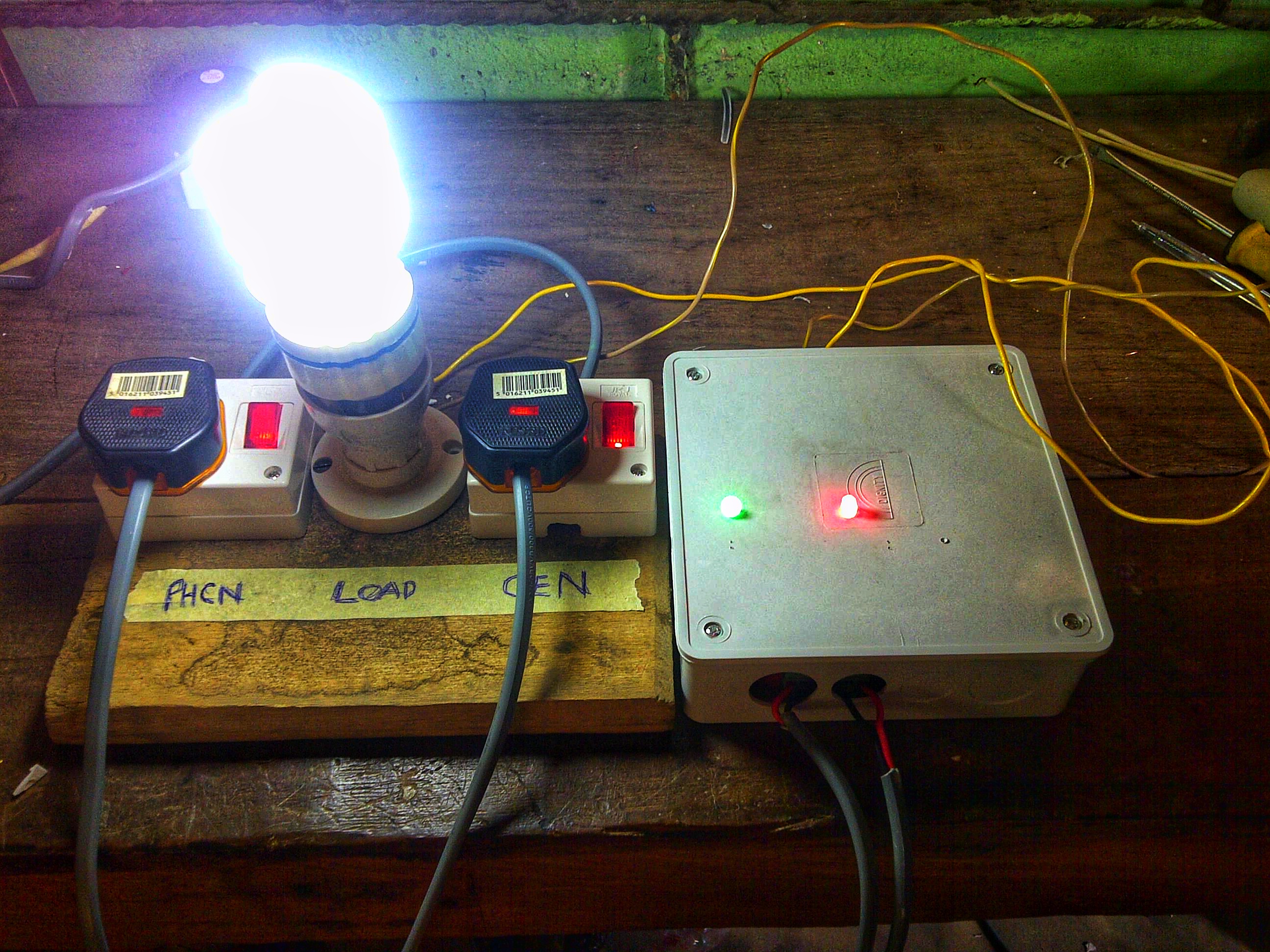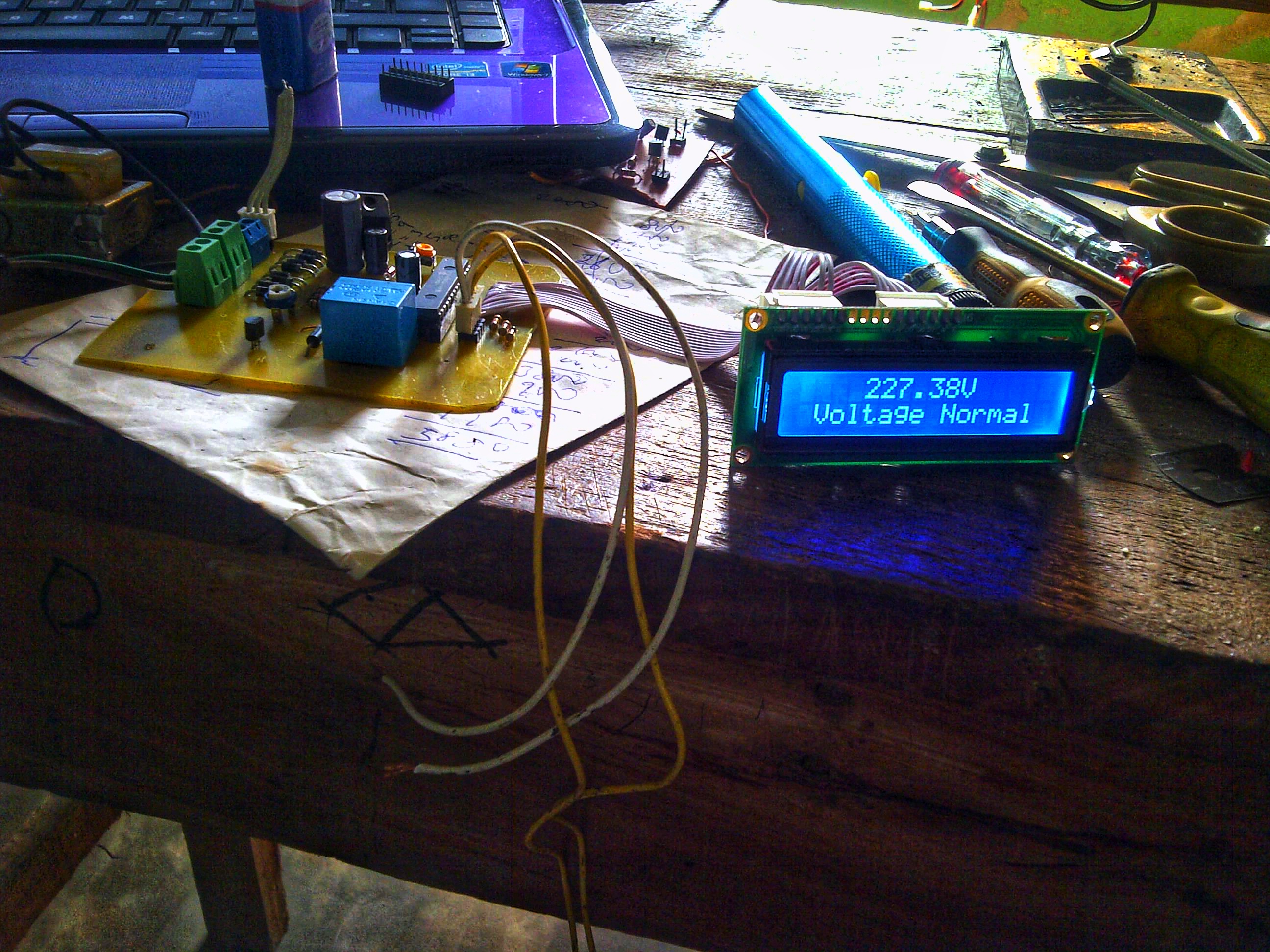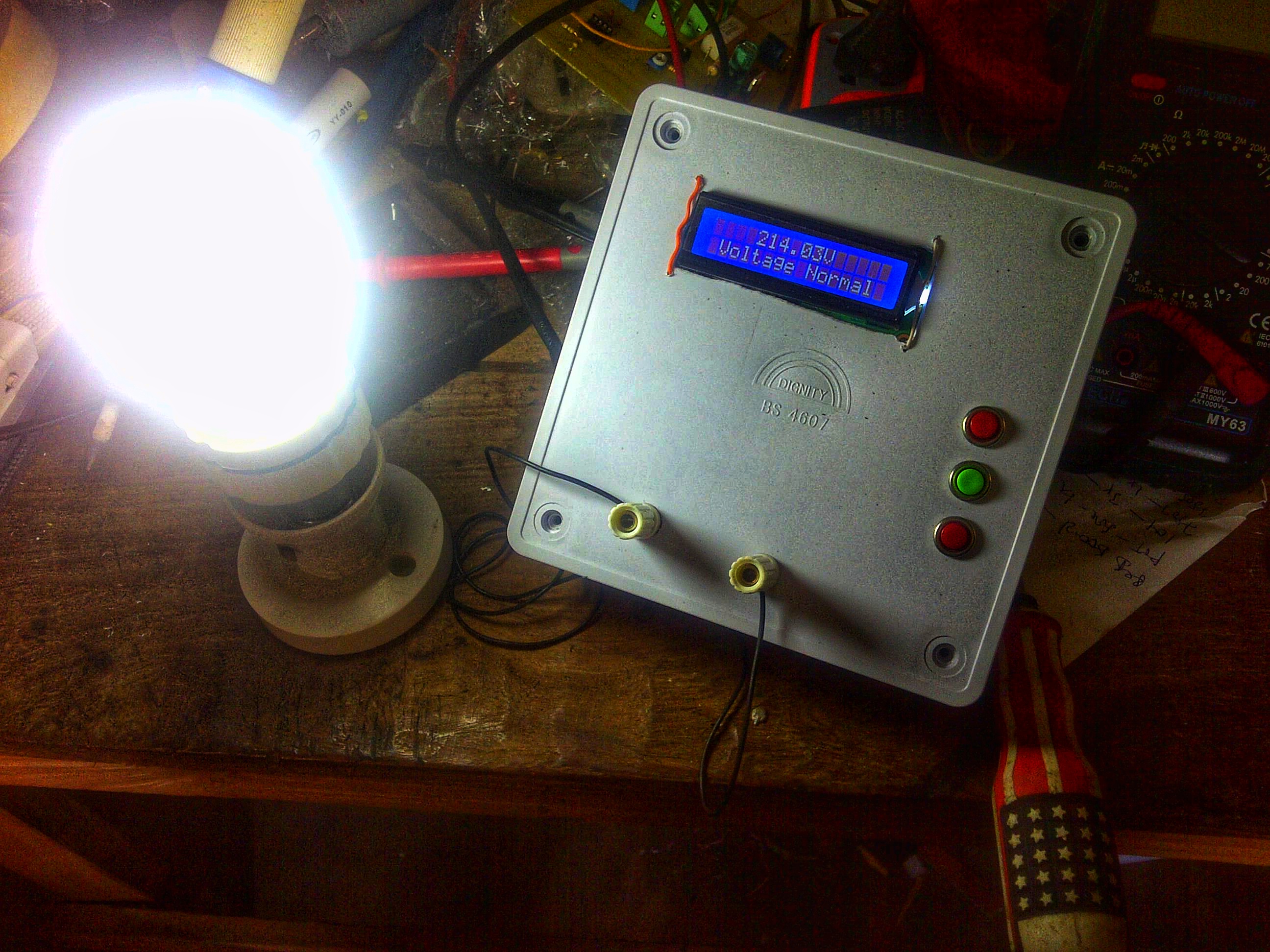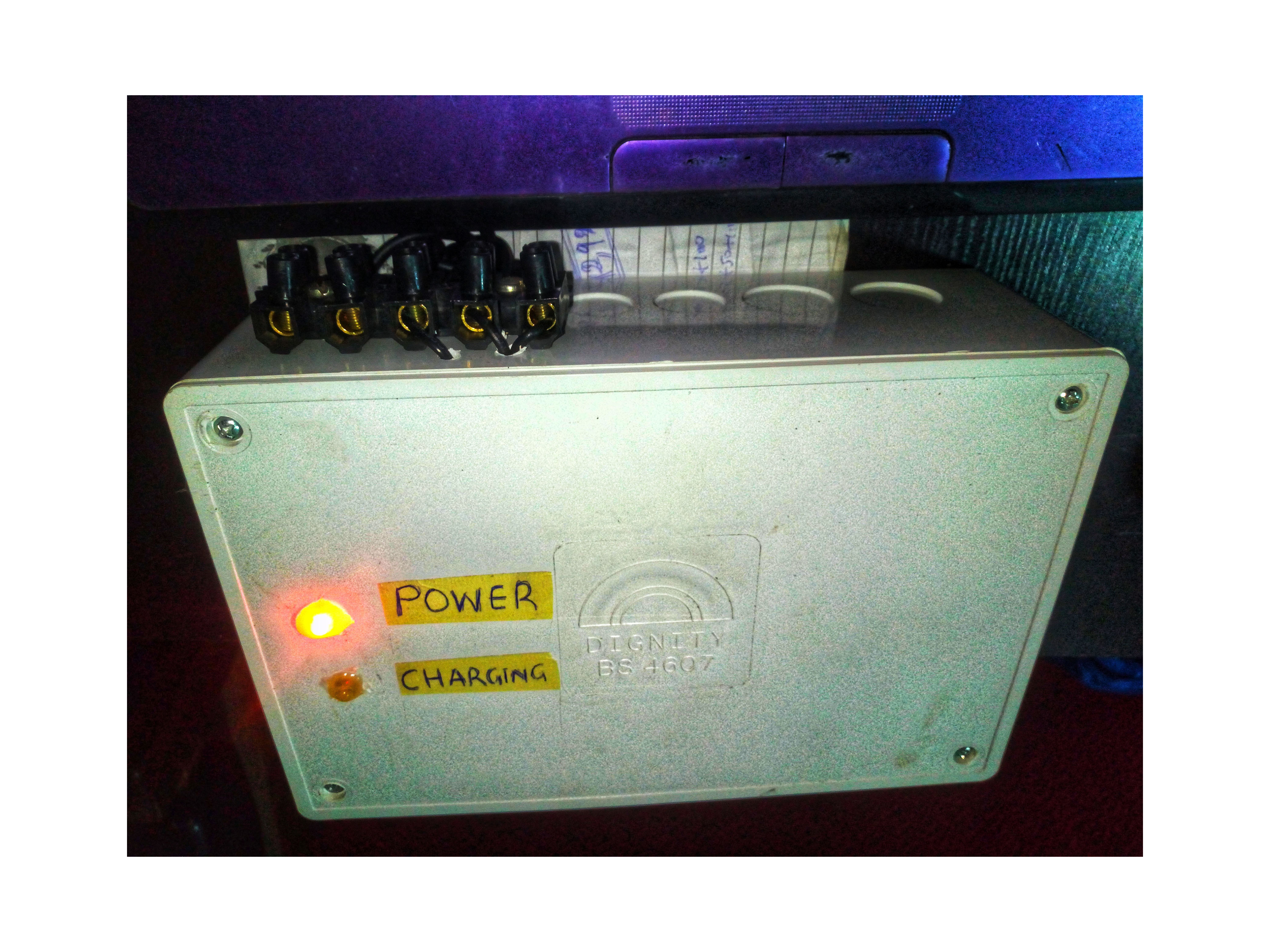

Project Overview
This project presents an automatic AC voltage switch designed to monitor an incoming supply and protect a connected load against under-voltage and over-voltage conditions.
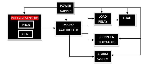
The documented system measures the input through a voltage-sensing and signal-conditioning stage, converts the signal for the microcontroller, displays a digital representation on an LCD and controls a load relay. User-defined minimum and maximum limits are stored in the microcontroller EEPROM.
How the System Works
- The incoming supply is passed through the documented voltage-sensing and signal-conditioning stages.
- The conditioned signal is converted for the microcontroller and represented as a digital voltage reading.
- The measured value is continuously compared with the stored minimum and maximum thresholds.
- If the supply moves outside the permitted range, the load relay disconnects the appliance.
- The system continues monitoring and restores the load when the voltage returns to the acceptable range.
System Architecture
◆AC SupplyVoltage source
→
◆Voltage SensorSignal conditioning
→
◆ADC / ControllerMeasurement & comparison
→
◆RelayLoad protection
→
◆LCDVoltage indication
Project Gallery
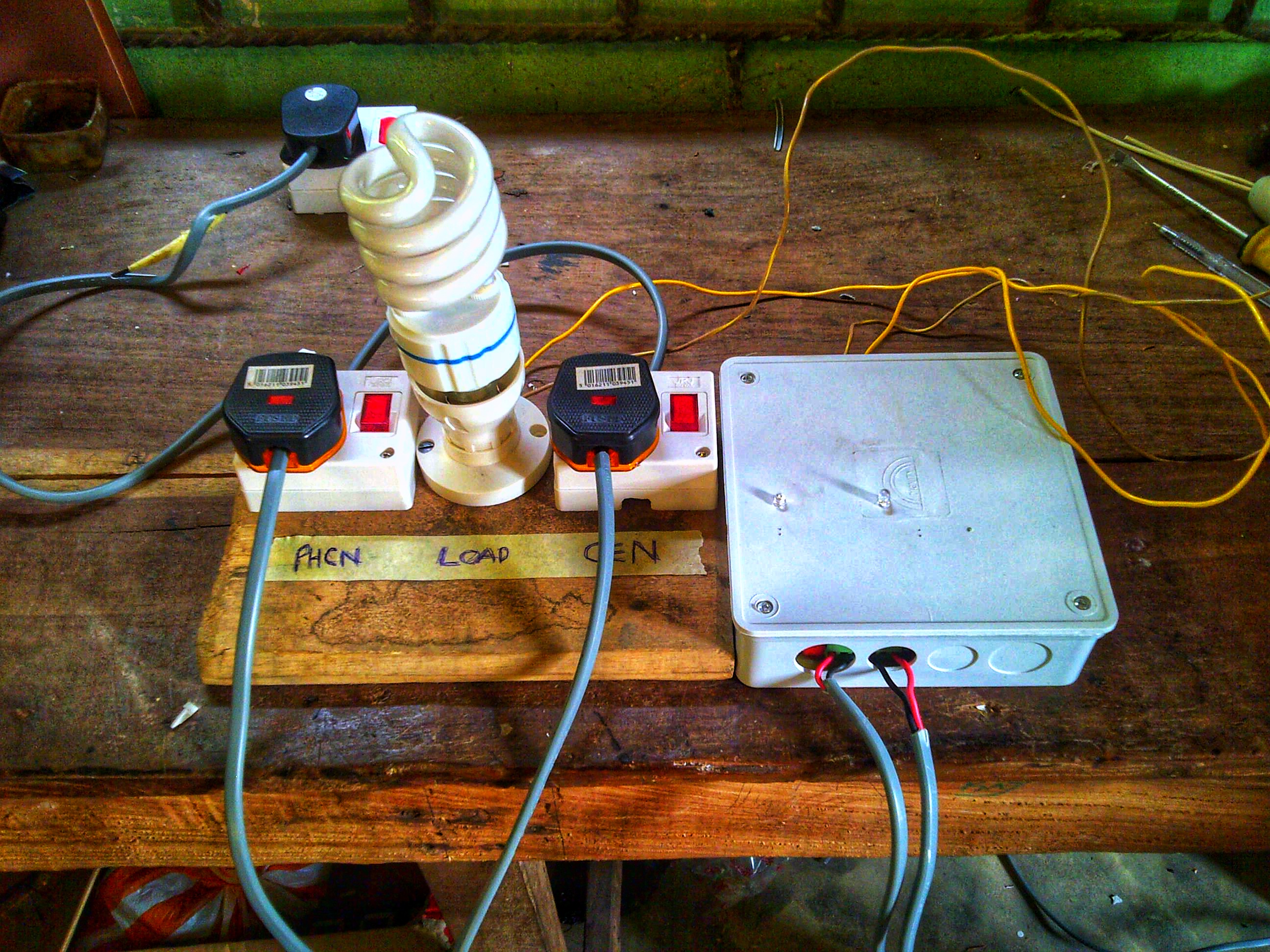
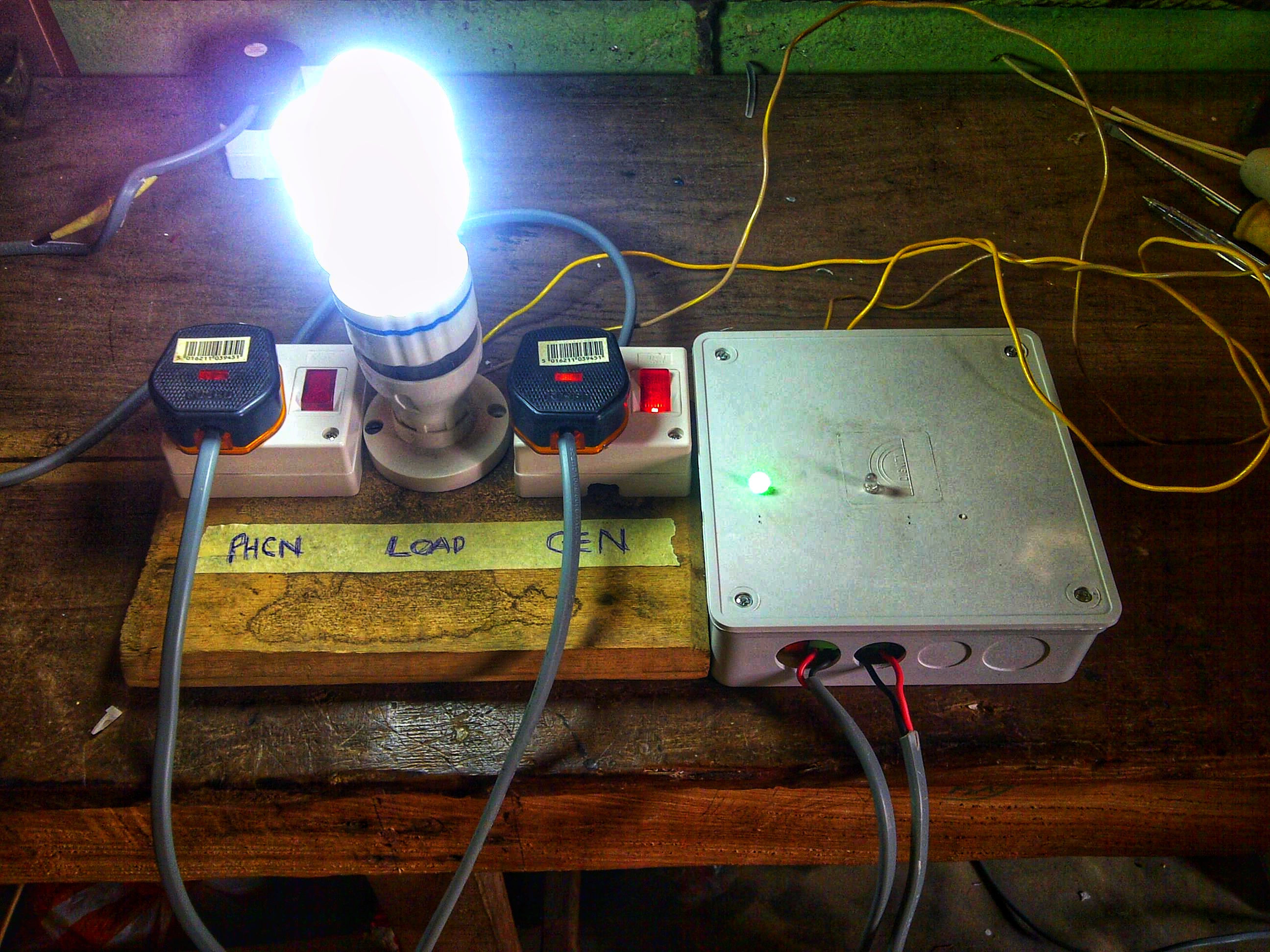
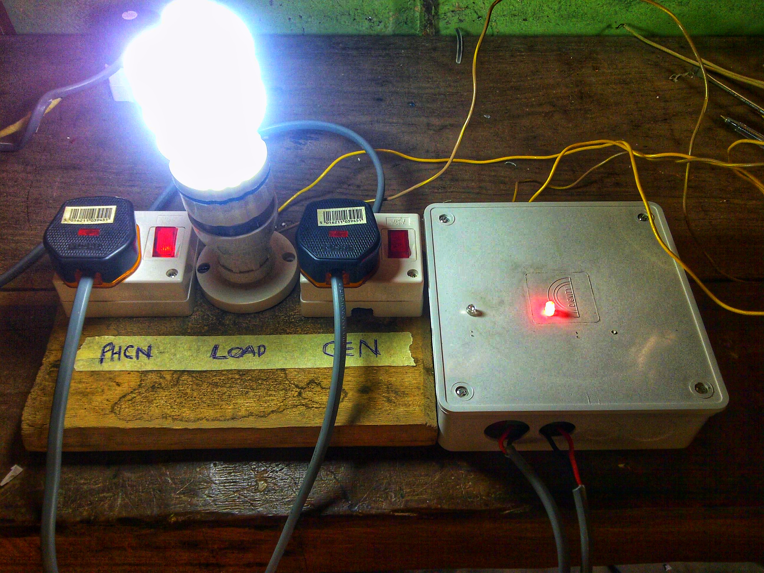
Actual project photographs and technical images.